 .home page .back Tutorials. GA Planes
Seven main gauges are instrumental to the pilotage of a GA plane. The first six are located just in front of the pilot, on the panel, with, from left to right, and above to bottom, the airspeed indicator, the attitude indicator (or artificial horizon, or AI), the altimeter, the turn coordinator (with the turn-and-slip indicator), the heading indicator, and the vertical speed indicator (or VSI). The remaining one gauge is the tachometer, which is located to the bottom left of the panel. Each of those seven gauges have marks, tunings and sets which are of interest for a GA pilot to know
The first six primary gauges are either slated to a gyroscopic system, or the air pressure, or 'Pitot' system of the plane. The airspeed indicator, the altimeter and the vertical speed indicator are slated to the Pitot system, a set of two sensors -the Pitot tube proper, and a sensor for the static pressure- used to probe the dynamic, or static air pressure around the plane. That set of gauges and sensors mostly work like a barometer. The attitude indicator, the heading indicator and the turn coordinator (with the turn-and-slip indicator) are each related to a gyroscope. A gyroscope is a wheel spinning inside a ring. That tool keeps its inclination whatever the pitch or bank of its support. Aboard a plane, that support is the plane. Thus, the pitch or bank of your plane, the rate of a turn, or the heading changes may be computed and displayed on your panel! All three gyroscopes are powered through a void pump linked to the plane's engine, as the gyroscope for the turn coordinator (with the turn-and-slip indicator) is further powered through a electrical engine which keeps working in case of a failure of the pump
Those seven gauges are described here in relation to the pilotage of a GA plane in VFR conditions, which means the first level of the degrees and qualifications a pilot may obtain and which allow him to fly as he keeps the visual view of the ground during a navigation. For as far as those -or more advanced versions of those- are related to the pilotage of more advanced GA planes, or commercial ones or airliners, the description of those, when necessary, is given in the appropriate tutorials
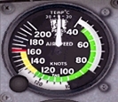 |
| a view of a GA plane's airspeed indicator |
The airspeed indicator helps the pilot to the awareness of the speed of the airplane. In a actual plane, the airspeed indicated is in knots (one knot is one nautical mile (NM) per hour) as it is indicating the 'indicated airspeed' of the plane. The indicated airspeed (or IAS) is the airspeed which you can read on the airspeed indicator. It is different of the 'true airspeed' (or TAS). The true airspeed is the true airspeed of the plane into the air. The IAS and the TAS differ between themselves mostly due to the fact that the density of the air is decreasing with the altitude. Thus, the 'absolute' -or actual- airspeed of the plane in the air is increasing the more the plane is flying in altitude, as the airspeed you'll read on the airspeed indicator is determined by the system of the gauge, which is based on a measured static pressure at the altitude of the plane, and the pressure due to the motion of the plane. The more the plane is flying in altitude, the less particles of air is reaching the system and the lesser the airspeed displayed on the gauge! The more the plane is flying high, the more the IAS will be lower to the TAS. The TAS is basically equal to the speed of the airplane relative to the ground, minus or plus the effect of a head or a tailwind, for example. To get an idea of what the average TAS of your airplane is, just fly your plane, at an average cruise altitude (some 5,500 or 6,500 ft) towards a VOR-DME, with the NAV engaged at the autopilot, and read the airspeed given at the DME gauge. The average TAS of the Cessna 172SP is of 113 kts. The TAS thus is the airspeed you'll use when you'll compute the time needed to perform a route! The difference which is extant between true, and indicated airspeed may be theorized into some formulae. As far as GA planes are concerned, one obtains TAS for a given altitude with adding to IAS 1 kt of speed for each 600 ft of altitude. As far as airliners are concerned, for a given flight level, just use the following formula: TAS=IAS&45;1/2FL. The IAS (which you have the airspeed indicator displaying in FS via the 'Realism Parameters' settings) is the one which you read on the gauge of the airspeed indicator as it is mainly of use during the plane's maneuvers, and as far as the limit airspeeds of the plane are concerned! The airspeed indicator gauge thus is arranged with colored arcs, and with marks. The green arc is showing the usual range of use for your plane. The lower end of the arc is where the plane will stall, without flaps. The higher end where the maximum usual airspeed is. The maximal usual airspeed if also called 'Vno'. The yellow arc, beyond, is showing the range of airspeeds your plane is allowed to when in calm air conditions. Where it ends is the airspeed never to excede (or 'Vne') under threat of structural damages to the plane. The Vne is further indicated by a red mark! The white arc of the airspeed gauge, at last, is showing the range of airspeeds at which you can use the whole of the flaps of the airplane! The higher end of the arc is the 'Vfe airspeed', which is the maximal airspeed to fly with the whole flaps out. The lower end of the white arc is the 'Vso airspeed' which indicates where the plane will stall, with the whole flaps
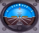 |
| a view of a GA plane's attitude indicator |
The attitude indicator (or artificial horizon, or AI) allows, as far as the pilotage of GA airplanes in VFR conditions is concerned, to check the visual clues the pilot is taking during a flight. A VFR-licensed pilot must fly with visual clues first! The attitude indicator, first gives clues about the inclination of the plane, and the angle of the bank. From the upper, white vertical mark, the white marks are pointing, from either side, to 10, 20, 30 and 60° as the white lines below the figured horizon are pointing to 15 and 45° respectively. The 45° tick may be used when you're banking a plane for a strong-banked turn. It will helps to make sure the plane is really on such a turn! Just check that the AI is pointing to the second white line under the horizon. As far as the pitch of the plane is concerned, the AI is divided, either side of the horizon into marks which are 10 and 20 degrees with smaller marks of 5 in-between. There mostly are of no use in VFR conditions
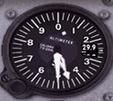 |
| a view of a GA plane's altimeter |
The altimeter of a plane is no more than a barometer. That barometer is fed with the Pitot system which is intaking the outside pressure. The variation of altitude, thus of the air pressure, is translated into the motion of the needles of the gauge, giving the pilot the altitude at which he is flying. The altitude is indicated in feet. The smaller needle is pointing to the thousands of feet, the larger one to the hundreths. Altitudes above 10,000 ft -which may be found a rare occurrence aboard a plane like a Cessna 172SP- are indicated by a white dot which is moving too, albeit much slower and indicating that your plane is above the 10,000-foot mark (mostly, in that case, when the dot has crossed the '1' mark!) On the example given in the illustration, your plane is flying at 4,500 ft of altitude (with the small needle between 4 and 5, and the large one on 5). The white dote is repeating of sort the indication and, in any case, is lying below the '1' mark, below 10,000 ft that is. Some planes may feature other systems of indications of the 10,000-foot mark, with some striated area appearing at an altitude below 10,000 ft. The altimeter, as a barometer, is tuned so to give the altitude relatively to the mean sea level ('MSL'). With the altitude and, generally, with the weather types, the air pressure is varying. The setting window allows for. On the ground, the altimeter settings, generally, when correctly set, makes that the altimeter is showing the altitude, in ft, of the terrain unto which you're lying. (for more about the setting of a altimeter, check at the varied texts of the site, when that settings are concerned)
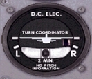 |
| a view of a GA plane's turn indicator (with a turn-and-slip indicator) |
The turn coordinator, the figure of a plane atop the gauge, is related to the standard-rate turns as the the ball located at the bottom of the gauge is related to the coordination of the turns, which constitutes the turn-and-slip indicator. When the wing of the figure plane, either side, is matching the white 'L' or 'R' tick, your plane is just performing a standard-rate turn, which means a 360-degree turn on a timespan of 2 minutes! This is mostly used during some maneuvers in the airport environment when it's of importance for both you and the controllers to have your plane perform a turn during a certain, ascertained time. More about that when appropriate in our tutorials. The turn-and-slip coordinator, or the ball, is an indication of whether a turn is correclty coordinated or not as a turn always needs an action by the pilot both on the stick (ailerons) and the rudder. check more at Level Flight, Climbs, Descents, Turns Aboard a GA Plane". The gauge's ball is lying on the opposite side of where the aircraft's nose is, whatever caused the orientation of the latter, like banking the plane and the aircraft's nose pulled to the side of the rising wing, or yawing the plane through the rudder, for example. When the ball is moving -or is- left, the aircraft's nose is moving -or is- left, and conversely
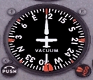 |
| a view of a GA plane's heading indicator |
The heading indicator is the gauge which is allowing to check towards what heading your plane is flying. It comes in complement of the magnetic compass, which, in a Cessna 172SP, is hanging to the center top of the panel. As the heading indicator is slated to a gyroscope, it's more stable than the compass, which is a mere magnetic compass, as the latter is difficult to read during turns, for example, or other maneuvers. The backlash to that is that the heading indicator is subject to a shift, function of the inherent precession of the gyroscopic system, a characteristic which makes that shift occurring. The pilot, during a flight thus will have to intermittently re-adjust the heading indicator indication with the one of the magnetic compass. A heading indicator shift does not excede 3 degrees for each 15 minutes of flight. To adjust the heading indicator with the compass, just use the knob to the lower left of the gauge. The heading indicator, generally, as far as the pilotage of GA plane under VFR conditions is concerned, is mostly used to check the heading, during a navigation, as the base, or in complement of, the visual landmarks the pilot is aiming to. The heading indicator is used too, along with the external landmarks, during the traffic pattern around a landing airport. That helps to check whether you're at the good heading during the legs of the pattern. The heading indicator is figuring a compass reading, with the North, East, West, and South marks indicated
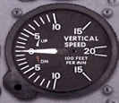 |
| a view of a GA plane's vertical speed indicator |
The vertical speed indicator is a gauge which tells at what rate a plane is gaining, or loosing altitude. At the 0 mark, the plane is flying horizontally. When the needle goes up, the plane is gaining altitude, when it goes down, the plane is loosing altitude! The graduations are to be added with 100 ft (5 is for the plane climbing or descending by 500 ft per minute, 10 by 1,000 ft per minute, etc). The usual climb, or descent rate of a Cessna 170SP is of 700 ft/mn. The vertical speed indicator mostly is not to used aboard a GA plane under VFR conditions as the pilot has first to use visual clues to determine whether its plane is climbing or descending, or even to set his plane into a climb, or a descent pitch
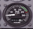 |
| a view of a GA plane's tachometer |
The tachometer is related to the functionment of the plane's engine. It's indicating the engine's rotation per minute, or RPM. Aboard a GA, fixed-pitch propeller plane like a Cessna 172SP, that gauge is mostly indicating to you the range of RPM you're engine is allowed to. The green arc is showing the values which cas be used while cruising. The red mark points to the maximum RPM useable, any prolonged used beyond the mark may damage the engine. The tachometer is used too during the approach and landing maneuvers as it allow to tune the throttle lever to a pre-determined value appropriate to such or such maneuver (1,700 RPM are to be applied during the final, when the plane descend to the runway, or about 2,100 RPM during the downwind leg of the traffic pattern. The values are to be added with 100 (25, for example, means that the plane's engine is rotating at a speed of 2,500 rotations per minute!)
Website Manager: G. Guichard, site Lessons In Microsoft Flight Simulator / Leçons de vol pour les Flight Simulator de Microsoft, http://flightlessons.6te.net.htm. Page Editor: G. Guichard. last edited: 5/27/2013. contact us at ggwebsites@outlook.com